As a key actuator component in hydraulic systems that achieves bidirectional linear motion, the mainstream single-rod double-acting hydraulic cylinder in the industry is manufactured with three core requirements in mind: "high precision, strong wear resistance, and strict sealing." In particular, the deep hole machining of the cylinder barrel and the precision machining of the piston rod are the technical core aspects that determine the product's lifespan and performance. Today, using this type of hydraulic cylinder as an example, and incorporating the "Design for Manufacturing (DFM)" concept, we will comprehensively break down the entire manufacturing process, from material selection and equipment selection to step-by-step processes, helping you understand the technological logic behind precision hydraulic components.
The core components of a single-rod double-acting hydraulic cylinder include the cylinder barrel, piston rod, piston, front cylinder head, rear cylinder head, seals, and connectors. Material selection must strictly match the processing technology and working conditions, which is a core embodiment of the DFM (Design for Manufacturing) concept:
Cylinder Barrel: Seamless steel pipes are preferred for the blank (a type of steel pipe without welds, with uniform material and high strength, eliminating the need for subsequent deep hole drilling, and adaptable to the "large length-to-diameter ratio" structural characteristics of the hydraulic cylinder). The material is mostly high-quality carbon steel or alloy structural steel. The cylinder bore processing accuracy needs to reach IT9~IT7 grade (IT is the international tolerance standard code; the smaller the number, the higher the accuracy. IT7 grade accuracy is higher than IT9 grade, ensuring precise fit between the cylinder bore and the piston, avoiding excessive internal leakage). Roundness (an indicator measuring whether the cross-section of the part is close to a perfect circle; the smaller the error, the more uniform the contact between the inner wall of the cylinder bore and the piston seal), and cylindricity (an indicator measuring whether the entire outer circle or inner hole of the part is uniformly cylindrical; the smaller the error, the smoother the piston movement) errors should not exceed 1/2 of the fitting tolerance. The straightness of the axis (an indicator measuring whether the central axis of the part is straight, with an error of ≤0.03mm over a length of 500mm, preventing piston jamming during movement) should be ≤0.03mm over a length of 500mm, and the surface roughness Ra=0.1~0.4μm (Ra is an indicator measuring the smoothness of the surface; the smaller the value, the smoother the surface. This range reduces seal wear and extends service life) (directly affecting the life of the seals). Piston Rod: The core load-bearing component. The preferred material is 35 or 45 steel (common high-quality carbon structural steel, with moderate strength and easy machinability); for applications involving severe impact and vibration, 55 steel or 40Cr alloy steel (an alloy structural steel with improved strength and toughness due to the addition of chromium, suitable for bearing high impact loads) is used. It requires heat treatment (a heat treatment process involving heating and quenching the steel, followed by high-temperature tempering, aiming to improve the overall performance of the material – ensuring both strength and a certain degree of toughness to prevent the piston rod from fracturing under stress) to a hardness of HB229~285 (HB is the Brinell hardness unit; the higher the value, the harder the material; this range ensures the piston rod is both wear-resistant and resistant to deformation); for corrosive or marine environments, stainless steel is used, with a hard chrome plating on the surface (approximately 0.05mm thick, electroplating a layer of chromium on the piston rod surface significantly improves wear resistance and corrosion resistance, preventing rust and wear). The fit tolerance is mostly H7/g8 or H7/f8 grade (in tolerance specifications, H represents the tolerance of the hole, g/f represents the tolerance of the shaft; the smaller the number, the higher the precision; H7/g8 provides a tighter fit, H7/f8 a slightly looser fit, both used to ensure the precise fit between the piston rod and the guide bushing, balancing sealing and smooth movement), with a surface roughness Ra=0.2~0.4μm, and roundness and cylindricity errors not exceeding 1/2 of the diameter tolerance. Piston and Cylinder Head: Pistons are commonly made from bar stock (cylindrical metal raw material) or cold-drawn bars (bars processed by cold drawing, offering high surface accuracy and uniform dimensions, reducing subsequent machining allowances and saving costs). The material is cast iron (an iron-carbon alloy with a high carbon content, high hardness, and easy casting, but poor toughness) or ductile iron (cast iron with a spheroidizing agent added, causing the internal carbon elements to be distributed in a spherical shape, resulting in significantly better toughness than ordinary cast iron, suitable for withstanding the repeated impacts of piston movement). The front and rear cylinder heads are made of carbon steel to ensure structural rigidity and welding compatibility.
Standard Parts: Sealing components (parts that prevent hydraulic oil leakage, such as O-rings and piston rings), lubrication nipples (interfaces for injecting lubricating oil), bearings (parts that reduce friction between moving parts), etc., prioritize products from established suppliers, focusing on the precision machining of core structural components.
The cylinder barrel uses a seamless steel pipe blank, avoiding the technical difficulties of deep hole drilling.
When the piston rod is designed as a slender shaft structure, a center hole (for positioning during lathe machining) and a steady rest support position (explained in subsequent processing steps) are reserved to reduce machining deformation;
Welded components (such as the rear cylinder head and cylinder barrel) have reserved locating tapered surfaces (tapered positioning surfaces to facilitate alignment during assembly) and pin holes (holes for inserting locating pins to ensure that parts do not shift during welding), ensuring coaxiality (the degree to which the center axes of the parts coincide).
The processing of single-rod double-acting hydraulic cylinders relies on specialized equipment and precision tooling (auxiliary processing tools). The core equipment must meet the requirements of deep hole machining, stable cutting of slender shafts, and high-precision finishing, specifically as follows:
Deep hole machining machine tool: The core feature is "workpiece rotation, tool feed" (to prevent tool deflection due to its slenderness); equipped with a powerful cooling and chip removal system (using high-pressure coolant to remove heat and chips generated during cutting, preventing tool overheating and damage, and preventing chips from scratching the workpiece), it can achieve front chip removal (used during fine boring, chips are discharged from the front of the workpiece) and rear chip removal (used during rough boring, chips are discharged from the rear of the workpiece). The coolant is double-filtered (magnetic oil filter (adsorbs iron chips) + foam oil filter (filters impurities)) to ensure the cleanliness of the oil. The machine tool's pressure head (a component used to support the tool holder, guide the tool, and clamp the workpiece) supports the tool holder, guides the tool, and clamps the workpiece. The rough guide bushing (a sleeve that guides the rough machining tool, preventing tool deflection during cutting) and the tool holder guide bushing (a sleeve that supports the tool holder, enhancing the rigidity of the tool holder) enhance the rigidity of the tool holder and prevent machining vibration.
Key tooling: Rough boring head (a tool used for rough machining holes, with a carbide front guide block and a cloth-reinforced plastic rear guide block, the former is wear-resistant, and the latter assists in positioning), fine boring head (a tool used for fine machining holes, adopting a floating structure that can automatically align with the center to ensure machining accuracy), roller burnishing head (containing tapered rollers, a tool that achieves finishing and strengthening by extruding the workpiece surface).
Equipped with an elastic tailstock center (a center on the lathe tailstock with a certain elasticity, which can support the part to ensure positioning without causing deformation due to excessive tightening) and an improved steady rest (an auxiliary device for machining slender parts on a lathe, supporting the part like a "bracket" to prevent vibration or bending, usually with three support blocks), used for rough turning (initial turning) and semi-finishing of piston rods; using reverse feed (the tool moves from the far end to the near end of the part, reducing bending deformation of the slender shaft).
Grinding equipment: Ordinary cylindrical grinding machine (a machine tool used for grinding the outer diameter of parts, equipped with an open center rest), centerless grinding machine (no need for center positioning, the workpiece is rotated and ground by the grinding wheel and guide wheel, suitable for mass production) (using through-feed grinding (the workpiece enters from one end of the machine and exits from the other end for continuous grinding) + support frame (an auxiliary device for supporting slender workpieces to prevent vibration)), used for precision grinding of the outer diameter of piston rods; double-wheel honing special device (can be modified from a lathe, using two inclined grinding wheels to finely grind the surface of the workpiece to achieve ultra-precision machining), to achieve ultra-precision finishing.
Rolling equipment: Piston rod special rolling head (containing 12 tapered rollers, a tool that strengthens the surface by extruding the surface of the piston rod), used for surface strengthening treatment.
Automatic welding machine: Circumferential seam welding machine (equipment used for welding circular seams, such as coaxial parts like cylinder barrels and rear cylinder covers, ensuring uniform welds), sleeve welding machine (equipment specifically used for welding sleeve-type parts), ensuring welding airtightness and coaxiality. Assembly and testing equipment: torque wrench (a wrench that can set the tightening torque, ensuring consistent bolt tightening force and preventing leaks due to loose bolts or damage to parts due to overtightening), press-fitting tools (tools used to press bearings and other parts into their installation positions, ensuring assembly accuracy), roughness tester (an instrument for measuring surface roughness), roundness tester (an instrument for measuring roundness error), pressure testing bench (equipment that injects high-pressure oil into the cylinder to check for leaks), ensuring assembly accuracy and product quality.
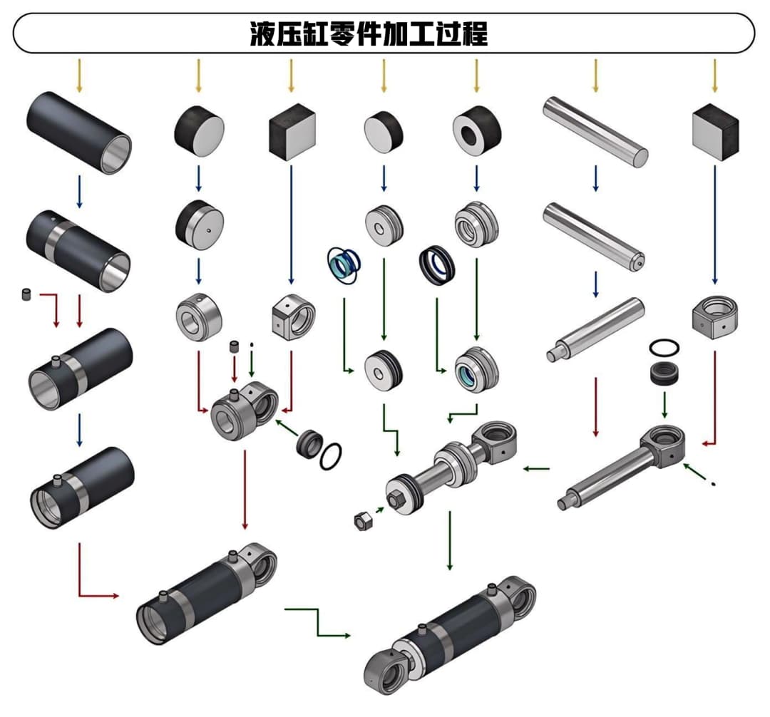
The manufacturing process of a single-rod double-acting hydraulic cylinder can be summarized into five main stages: "Raw Material Pre-treatment → Core Component Maching → Welding → Assembly → Testing". Each step requires strict control of process parameters (such as cutting speed and feed rate) to avoid common defects (such as hole misalignment and part deformation):
First Step: Raw Material Pre-treatment
Purchase seamless steel pipes (cylinder barrel), round steel (piston rod), and other blanks that meet the requirements. These are then straightened (a process of correcting the bending of the blank through pressure or heating to ensure subsequent processing accuracy) and derusted (removing surface rust to prevent scratching the workpiece during processing);
The cylinder barrel blank is cut to the design length using an automatic band saw (a saw that can automatically cut metal, with high cutting accuracy and efficiency), and the end face is deburred (removing sharp protrusions on the cut end face to prevent scratching the seals during assembly); the piston rod blank has a center hole drilled for subsequent processing positioning.
Second Step: Core Component Machining
(1) Deep Hole Machining of Cylinder Barrel (Rough Boring → Fine Boring → Roller Burnishing)
Rough boring (preliminary machining of the cylinder bore, removing most of the excess material, leaving allowance for fine boring): Use a rough boring head with double guide blocks, main cutting edge angle 60° (the angle between the cutting edge of the tool and the workpiece axis, 60° can reduce radial force and prevent tool deflection), removing most of the allowance (leaving 0.15~0.20mm for fine boring); using rear chip removal, high-pressure cooling oil (flow rate 300L/min, pressure 0.8MPa) is used to forcibly remove chips; cutting parameters: cutting speed 1.7~2m/s (the speed at which the cutting edge of the tool moves relative to the workpiece, a moderate speed can balance efficiency and tool life), feed rate 0.2mm/r (the distance the tool moves for each revolution of the workpiece, 0.2mm/r ensures stable cutting). Fine Boring (Fine machining of the cylinder bore after rough boring to ensure final accuracy and surface quality): Uses a floating fine boring head with automatic centering and diameter correction; the guide block must meet the requirements of "the front part matches the diameter after rough boring, the back part matches the diameter after fine boring, and the circumferential dimensions are consistent"; uses forward chip removal, cooling oil flow rate of 200 L/min; cutting parameters: feed rate 2~2.5 mm/r, cutting speed increased by 20% compared to rough boring.
Roller Burnishing (A process that smooths and strengthens the cylinder bore surface by pressing the roller burnishing head against it): Burnishing allowance (thickness of material removed during burnishing) is controlled at 0.08~0.12 mm (excessive interference fit can easily cause peeling and cracking, while insufficient interference fit cannot eliminate tool marks); cutting speed 1.3~1.7 m/s, feed rate 0.25~0.3 mm/r; roller burnishing head roller radius R=2 mm, all roller size tolerances ≤0.005 mm. After burnishing, the cylinder bore surface roughness Ra≤0.1 μm, forming a cold work hardening layer (a surface layer where the metal undergoes plastic deformation after rolling and pressing, increasing hardness and enhancing wear resistance and fatigue life), significantly improving hardness and wear resistance.
(2) Piston Rod Machining (Turning → Grinding → Finishing/Strengthening)
Turning (The process of machining the outer diameter of the piston rod using a lathe, divided into rough turning and fine turning): Uses "elastic tailstock center + improved steady rest" clamping; 4×20mm steel wires are placed between the jaws and the workpiece (line contact adjustment direction to prevent workpiece deformation caused by excessive clamping force); when the slenderness ratio > 1:80, add wooden support blocks (wooden blocks that assist in supporting the workpiece, reducing vibration and preventing scratching of the workpiece) to dampen vibrations; uses reverse feed to reduce cutting deformation; rough turning tool main cutting edge angle 75°, surface roughness after machining Ra=1.6~3.2 μm. Grinding (fine machining of the piston rod's outer diameter using a grinding machine to further improve accuracy and surface quality): A conventional cylindrical grinding machine is used with an open-type center rest (a device for supporting slender workpieces, which can be opened for easy workpiece clamping; the support blocks are made of nylon or hardwood to prevent scratching). The workpiece rotation speed is relatively low (to prevent vibration), and the grinding depth is small (to avoid workpiece overheating and deformation). A centerless grinding machine uses through-feed grinding, with the workpiece center below the line connecting the grinding wheel and the regulating wheel (to ensure the grinding wheel presses the workpiece against the regulating wheel, preventing vibration), and is equipped with multiple support rests. After fine grinding, the surface roughness Ra = 0.2~0.4μm.
Finishing/Strengthening (processes to further optimize surface quality or improve surface strength):
Double-wheel honing (a process of ultra-fine grinding the piston rod surface using two inclined grinding wheels): The grinding wheels are installed with opposite inclinations, with a crossing angle α = 27°~35° (the angle between the grinding wheel axis and the workpiece axis, affecting grinding efficiency and surface quality). The grinding wheel grit size is W10~W20 (the smaller the grit size, the finer the abrasive particles on the grinding wheel surface, and the smoother the processed surface). After processing, Ra = 0.01~0.04μm, and cylindricity errors can be corrected.
Roller burnishing (a process of pressing the piston rod surface with a roller burnishing head to improve surface hardness and wear resistance): Burnishing allowance 0.01~0.015mm, spindle speed 500~600r/min (workpiece rotation speed), feed rate 0.3mm/r; after roller burnishing, surface roughness Ra < 0.1μm, and hardness is increased from HB162~190 to HB220~233. Step 3: Welding Process – Ensuring Structural Strength and Coaxiality: Before welding, clean the workpiece welding surface (free of oil and rust to ensure weld strength). Use locating pins + tapered surface positioning (inserting locating pins into pinholes and fitting the tapered surfaces together to ensure the parts are aligned during welding and prevent displacement) to ensure coaxiality; the cylinder barrel and rear cylinder head are welded using a circumferential seam welding machine. The clamping force (force used to fix the workpiece) during welding is controlled at 8000~12000N (adjusted according to the workpiece diameter to avoid damaging the workpiece or insufficient clamping leading to welding displacement); after welding, press-fit the bearing while still hot (the process of pressing the bearing into the installation position; operating while hot utilizes the thermal expansion and contraction of the metal, making it easier to install the bearing). After cooling, check the weld for cracks and pores (welding defects that can lead to oil leakage or insufficient strength). Step 4: Assembly Process – Precise Control of Sealing and Fit: Seal installation: The sealing groove (the groove used to install the seal) must be clean and free of burrs and scratches. Install the piston ring, felt ring, etc., into the groove, avoiding twisting (twisting of the seal can lead to oil leakage); pre-lubrication treatment: apply system oil (the hydraulic oil used when the cylinder is working; applying it in advance reduces friction during assembly and prevents seal wear) to all surfaces in contact with hydraulic oil; sub-assembly assembly: the piston rod and piston are locked together with a nut, ensuring the axial runout of the shaft shoulder (the runout error of the shaft shoulder end face relative to the axis, ≤0.02~0.04mm, to prevent piston displacement after assembly) ≤0.02~0.04mm; final assembly: install the piston-rod sub-assembly into the cylinder barrel, and tighten the threaded connection between the front cylinder head and the cylinder barrel with a torque wrench to ensure reliable sealing. Step 5: Finished Product Inspection and Packaging — Final quality control before shipment: Precision inspection: checking the dimensional tolerances (allowable deviation range of part dimensions), roundness, cylindricity, and surface roughness of the cylinder bore and piston rod; Performance testing: conducting pressure testing (injecting high-pressure oil into the cylinder, maintaining it for a period of time, and checking for leaks to ensure sealing performance), and stroke accuracy testing (checking the deviation between the actual length and the designed length of the piston rod extension and retraction to ensure motion accuracy) (smooth movement without jamming); Anti-rust packaging: surface anti-rust treatment (such as applying anti-rust oil and packaging with anti-rust paper to prevent rust during transportation and storage) followed by sealing to prevent scratches during transportation. Note: A single-acting double-acting hydraulic cylinder manufactured with standardized processes and regularly maintained can have a service life of several years or even longer.
Cylinder barrel deep hole machining deviation: Use workpiece rotation + double guide block boring head, pressure head guide sleeve and center support to enhance tool bar rigidity, and perform two-stage cutting after rough boring to ensure uniform allowance; Piston rod turning vibration and deformation: Elastic tailstock + three-support steady rest + reverse feed to reduce cutting stress and vibration; Surface peeling after rolling: Control rolling allowance (0.08~0.12mm), pre-machining surface roughness Ra=1.6~3.2μm, avoid excessively deep valleys (excessively deep valleys will prevent the metal from filling during rolling, resulting in peeling); Coaxiality exceeding tolerance after welding: Use locating pins + tapered surface positioning, straighten in time after welding (correct deformation caused by welding), and control clamping force to avoid workpiece deformation.
The single-rod double-acting cylinder (front cylinder head threaded connection, rear cylinder head welded) introduced today is a general-purpose solution. In actual production, the process needs to be adjusted according to the cylinder type: Tie-rod cylinder: The cylinder barrel and cylinder head are connected by tie rods (long bolts connecting the cylinder head and cylinder barrel), no welding is required, and the focus is on controlling the tie rod pre-tightening force (the tightening force of the tie rod, too loose will cause oil leakage, too tight will damage the cylinder barrel); Telescopic cylinder: Multi-section cylinder barrel nesting design, requiring ensuring the coaxiality and smooth extension and retraction of each section (avoiding jamming between sections); High-pressure cylinder: High-strength alloy material is selected, and the cylinder bore adopts the "precision boring + multiple rolling" process to enhance surface strength (to withstand higher hydraulic pressure).


 IPv6 network supported |
Sitemap |
Xml |
blog |
Privacy Policy
IPv6 network supported |
Sitemap |
Xml |
blog |
Privacy Policy

 en
en