en
en 


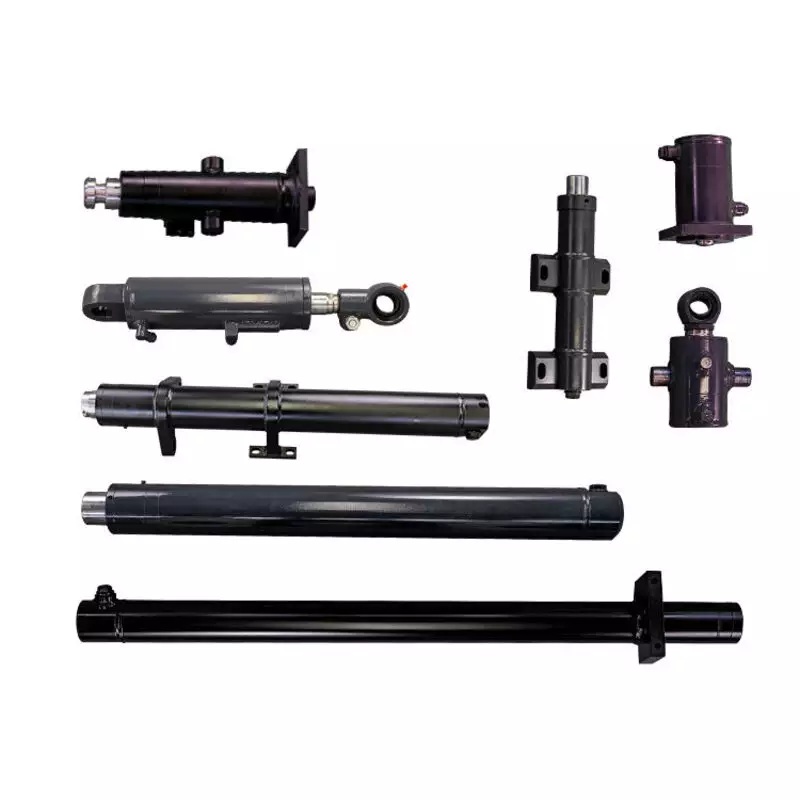
Safety Tip: Always verify exact equipment dimensions to ensure reliable hoist operation and technician protection.
You must evaluate four critical specifications when choosing a replacement unit: bore size, stroke length, mounting type, and pressure rating. Matching these parameters keeps your auto lift safe and prevents dangerous operational failure.
Inspect your equipment daily for clear diagnostic signs of wear. You need an immediate component swap when you notice hydraulic fluid streaks along the barrel, weeping around rod seals, or pooling at the base. Operating a leaking cylinder compromises lifting capacity and threatens worker safety. Installing a certified lift hydraulic cylinder protects mechanics. You should inspect each hydraulic cylinder base and check all hydraulic cylinders regularly to maintain stable vehicle elevation throughout your service bay.
Key Takeaways
-
Inspect auto lifts daily for fluid leaks and vehicle drift to spot cylinder failure early.
-
Measure bore diameter, stroke length, and pin sizes accurately before buying a replacement cylinder.
-
Match the cylinder pressure and weight ratings with your pump system to ensure safe operation.
-
Choose high-quality cylinders with hard chrome plating and sturdy seals to prevent future wear.
Identifying Signs of Auto Lift Cylinder Failure
Recognizing Hydraulic Fluid Leakage Points
Regular visual inspections help you catch early physical symptoms of component failure on your auto lift. Worn hydraulic seals allow pressurized hydraulic fluid to escape during daily shop operations. You can spot physical damage by looking for specific key signs across the assembly:
-
Examining Fluid Streaks and Pools: Inspect the cylinder barrel surface, areas surrounding the rod seals, and the cylinder base for fluid traces or accumulation beneath the component.
-
Evaluating Piston Rod Integrity: Check the rod surface for signs of rust, pitting, or scoring, which can ruin the seal boundary and cause hydraulic fluid loss.
-
Inspecting Rod Seals: Check for visible wear, extrusion, or physical deterioration on the external seal boundary.
External dirt creates grit and causes internal contamination inside the fluid reservoir. Damaged hydraulic seals allow constant leaking along the piston rod and cylinder body. Performing an early inspection prevents the sudden need for an emergency cylinder repair.
Assessing Pressure Loss and Drift Issues
Alert: A leaking cylinder creates extreme safety risks during vehicle lifting. Unintended pressure loss destabilizes your hoist structure and threatens technician safety.
You must differentiate between external fluid loss and internal hydraulic pressure loss during routine shop maintenance. Internal bypass failure occurs when fluid passes degraded internal hydraulic seals. This internal leaking issue lowers lifting force while the outer cylinder shell remains completely dry. Meanwhile, external leaking problems drop overall fluid reservoir levels rapidly.
|
Diagnostic Criteria |
External Rod Seal Leakage |
Internal Bypass Leakage |
|---|---|---|
|
Fluid Destination |
Escapes outside the cylinder housing |
Remains inside, bypassing internal sealing boundaries |
|
Visual Evidence |
Fluid accumulation, streaks, or wetness on rod/gland; dropping fluid level |
Cylinder exterior stays completely dry |
|
Performance Symptoms |
Visible fluid loss in fluid reservoir |
Load drift, diminished force, poor holding capacity, elevated operating temperature |
|
Verification Method |
Direct visual inspection of external components |
Controlled isolation procedures and pressure testing |
Slow uncommanded vehicle descent indicates internal component wear. You must address these performance issues immediately during regular system maintenance to maintain safe working conditions.
Measuring Hydraulic Cylinder Dimensions
Accurate measurements guarantee a safe fit for your replacement lift hydraulic cylinder. Small dimensional errors cause installation delays, severe seal damage, and structural binding. You must collect precise physical dimensions before ordering any replacement unit for your shop hoist application.
Using proper tools simplifies this process. Standard shop measuring equipment helps you identify exact specifications quickly:
|
Tool Category |
Primary Function / Application |
Precision & Tolerance Requirements |
|---|---|---|
|
Digital & Dial Calipers |
Measures bore and rod diameters |
Essential where precise fit and tight tolerances are critical |
|
Vernier Calipers |
Measures smaller components without batteries |
Provides mechanical accuracy; serves as a reliable backup |
|
Micrometers |
Measures cylinder rod diameters |
Delivers high accuracy for tolerances within thousandths of an inch |
|
Bore Gauges |
Measures inner barrel diameter & detects wall irregularities |
Extended probe allows deep readings to ensure seal alignment |
|
Measuring Tapes |
Determines overall cylinder length and stroke |
Requires a durable, corrosion-resistant blade to maintain accuracy |
|
Straight Edges |
Detects warping or bending along cylinder rods |
Identifies minor deviations to prevent seal wear and leaks |
|
Seal Identification Kits |
Identifies unknown seal types and dimensions |
Uses gauges and charts to match cross-section and profile specs |
You can also use additional basic tools and reference materials during your evaluation:
-
Rulers or Calipers: Use these items to determine the precise diameter of fluid port openings.
-
Manufacturer Specifications: Check these documents to identify exact numerical tolerances that you cannot easily measure directly in field conditions.
Determining Bore Diameter and Rod Size
Determining the inner bore diameter and the outer rod size ensures your auto lift achieves its rated lifting capacity. The internal bore diameter dictates overall lifting force under pressure, while the piston rod provides structural rigidity against heavy vehicle loads.
Thoroughly wipe down the components prior to taking any measurements. Removing contaminants such as grease, grime, or debris ensures that the jaws of the measuring caliper sit completely flush against the bare metal surface for an accurate reading.
Follow this exact procedure to measure the piston rod diameter without removing the cylinder:
-
Ensure the rod surface is thoroughly wiped down to remove any dirt or grease.
-
Position the digital caliper on a non-worn segment of the rod, typically near the gland wiper area rather than the middle.
-
Perform two distinct measurements rotated 90° from each other at three different positions along the clean area.
-
Log the lowest measurement captured to account for potential rod wear.
To find the internal bore diameter on working hydraulic cylinders, measure the outer barrel casing diameter and subtract the double wall thickness of the steel barrel. You can also measure the internal piston seal outer diameter directly if you disassemble the unit for maintenance.
Measuring Stroke Length accurately
Stroke length defines the total distance the piston travels from full retraction to full extension. Incorrect stroke lengths cause incomplete vehicle lifting or structural frame collision. You must calculate this metric carefully on fully retracted and fully extended equipment.
Follow these simple steps to measure the exact stroke length:
-
Establish a consistent fixed reference point on the cylinder structure.
-
Measure the distance from the established reference point to the rod at its maximum point of extension to obtain the extended length.
-
Measure the distance from the same reference point to the rod when it is completely collapsed to obtain the retracted length.
-
Subtract the total retracted length from the total extended length to calculate the exact stroke length.
Formula:
stroke length = extended length - retracted length
This basic calculation gives you the operational travel distance needed for your lift system.
Measuring Retracted and Extended Lengths
Retracted length represents the total overall length of the unit when completely collapsed. Extended length represents the maximum total length when the rod fully projects outward. These dimensions ensure proper frame alignment and mounting pin positioning within your auto lift housing.
You must measure the pin-to-pin distance on fully collapsed units to establish baseline dimensions. Follow this reliable technique on retracted hydraulic cylinders:
-
Ensure the hydraulic cylinder is in a fully retracted position.
-
Measure the distance starting from the center of the first mounting pin (or mounting surface) directly to the center of the second mounting pin.
Confirming center-to-center distances prevents binding inside lift columns. Matching these physical specs protects tie rod hydraulic cylinders and welded cylinders from premature structural stress. Always double-check your readings before purchasing a new single-acting or double-acting unit.
Matching Mounting Styles and Port Configurations
You must select the correct mounting style to attach your new component safely. Common hoist mounts include clevis ends, cross-pin eyes, and threaded rod ends. Clevis mounts use a fork and pin design to allow pivoting movement during operation. Cross-pin eyes slide directly over mounting studs inside the hoist posts. Threaded rod ends screw into matching mechanical adapters. Inspect your old hardware for wear before installing a replacement component.
Clevis, Pin, and Threaded Mount Types
Mechanical mounts secure the cylinder body inside your hoist frame. You need to match the exact pin diameter and ear spacing of your original equipment. A loose pin fit creates slop and bends the mounting ears over time. A tight fit prevents smooth pivoting and causes premature rod binding. Align the mounting holes precisely to prevent uneven force distribution across the pins.
Port Sizes, Threading, and Valve Specifications
Matching fluid port configurations prevents high-pressure fluid leaks and operational failures. You will encounter three standard port thread styles on shop equipment:
|
Thread Type |
Sealing Method |
Primary Benefit |
|---|---|---|
|
NPT |
Tapered threads with sealant |
Standard fit for general equipment |
|
SAE / ORB |
Straight threads with O-ring |
Superior high-pressure sealing |
|
JIC |
37-degree flared seat |
Excellent vibration resistance |
Pro Tip: Never force mismatched thread types into a hydraulic cylinder port. Check your port size with a thread gauge to prevent thread damage.
Verify that integrated velocity fuses match your hydraulic system specifications. Correct valve alignment controls fluid flow during emergency drops.
Structural Clearance and Frame Fitment
You must verify the spatial constraints within your specific auto lift frame structure. Tight mechanical enclosures leave minimal clearance for fluid lines and mounting hardware. Measure the surrounding frame interior to ensure the hydraulic cylinder shell fits without rubbing against steel plates.
Always check valve clearance during full stroke travel. Incorrect positioning can crush hydraulic fittings against the inner frame. Evaluating these physical dimensions helps you satisfy specific application requirements for your shop equipment. Proper fitment guarantees reliable operation under heavy vehicle loads.
Matching Load Capacity and Operating Pressure
You must match hydraulic cylinder load capacity with your auto lift specs to guarantee shop safety. Oversized or undersized components cause structural binding or total system failure.
Verifying Auto Lift Weight Ratings
You need to verify the total weight capacity of your lift before purchasing replacement components. Auto lifts require hydraulic components that handle maximum rated vehicle weights easily. Standard industrial guidelines demand that hydraulic lift designs incorporate a base safety capacity of 150% relative to the specified load rating. This extra margin protects technicians during daily vehicle lifting operations.
You must calculate maximum lifting force using the surface area of the internal piston and system pressure:
force = pressure x piston area
Never operate equipment beyond its engineered boundaries. Matching components correctly ensures your hoist raises heavy trucks and cars safely. Different lifting scenarios demand distinct safety margins to maintain structural stability:
|
Lifting Scenario |
Standard Working Load (% of Max) |
Applicable Safety Factor Margin |
|---|---|---|
|
Standard Static Operations |
75% – 80% |
1.25 : 1 |
|
Shop Press / Industrial Force |
60% – 70% |
1.4 : 1 to 1.6 : 1 |
|
Overhead or High-Risk Lifts |
50% or below |
2.0 : 1 minimum |
|
Asymmetrical / Unknown Weights |
50% or below |
2.0 : 1 minimum |
Selecting hydraulic cylinders with appropriate safety margins prevents premature mechanical failure during service routines.
Aligning Cylinder PSI with System Requirements
Your hydraulic pump generates high pressure to raise heavy vehicle loads. You must match cylinder pressure ratings with pump relief valve settings. Installing a low-pressure unit on a high-PSI system causes catastrophic seal blowout and structural barrel warping.
Check the manufacturer rating plate on your power unit. Ensure your replacement component rating exceeds the maximum system pressure. Proper pressure alignment keeps your fluid lines intact and maintains steady lifting speeds.
Always review your specific application requirements before confirming any component order. This careful verification step prevents dangerous pressure overloads during heavy lifting operations.
Single-Acting vs Double-Acting Systems
Auto lifts utilize distinct internal mechanical configurations. You must identify whether your equipment uses single-acting or double-acting force mechanics. Single-acting auto lift cylinders comprise a cylinder body, a single fluid port, a piston, and a rod. They provide linear force in one direction and offer a cost-effective design. Conversely, double-acting units feature dual ports located at opposite ends. These components utilize bidirectional hydraulic force to power both lift and lower functions without relying on passive external loads.
Understanding operational steps helps you choose the correct replacement part:
-
Single-Acting Operational Steps:
-
Fluid enters the lower port to push the piston rod outward.
-
When pressure releases, oil returns to the pump reservoir via external load force, gravity, or an internal spring.
-
-
Double-Acting Operational Steps:
-
Fluid enters the bottom port to extend the piston rod under pressure.
-
Fluid enters the top port to retract the rod, granting full speed control during high-cycle shop operations.
-
The structural and functional differences dictate how your hoist responds under load:
|
Feature Category |
Single-Acting Cylinders |
Double-Acting Cylinders |
|---|---|---|
|
Structural Features |
Single port design; smaller housing; may include an internal return spring; fewer total internal parts. |
Two ports (top and bottom); dual fluid chambers; lacks internal return springs. |
|
Operational Mechanics |
Uses fluid pressure exclusively for extension; relies on gravity, load weight, or springs for retraction. |
Uses alternating hydraulic fluid pressure for both extension and retraction. |
|
Control & Direction |
Force applied in one direction; less predictable or slower retraction cycles. |
Bidirectional push-and-pull power; offers higher precision, speed, and overall movement control. |
Selecting the proper design keeps your lift operating smoothly. Single-acting components suit gravity-down two-post lifts perfectly. Double-acting units deliver consistent control for specialized commercial equipment in every shop application.
Selecting a Quality Lift Hydraulic Cylinder
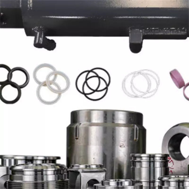
Rod Chrome Plating and Seal Standards
You must evaluate component materials to guarantee long service life in demanding shop environments. Premier manufacturers construct piston rods with hard chrome plating to resist rust, pitting, and abrasive particle contamination. Smooth rod surfaces extend the working lifespan of internal components and maintain steady movement.
High-pressure polyurethane hydraulic seals contain pressurized hydraulic fluid inside the barrel. Top-tier hydraulic seals withstand rapid pressure spikes without changing shape or cracking. Quality hydraulic seals block external dirt and prevent internal fluid leakage. Selecting upgraded hydraulic seals protects internal components and reduces your routine equipment maintenance needs.
Welded vs Tie-Rod Cylinder Designs
You will choose between two primary structural designs for shop hoists:
-
Tie Rod Hydraulic Cylinders: These units use external threaded steel rods to secure both end caps to the barrel. Mechanics dismantle tie rod hydraulic cylinders easily for bench rebuilding, but the exterior frame consumes extra spatial clearance inside hoist legs.
-
Welded Hydraulic Cylinders: These components weld end caps directly to the heavy-wall steel barrel. Welded housing styles offer a compact footprint and sleek outer body.
Selecting a smooth welded lift hydraulic cylinder provides maximum structural rigidity. The narrow profile fits easily inside tight lift post enclosures for your auto hoist application.
Kaixin Precision Manufacturing and Safety Compliance
Kaixin builds high-durability hydraulic cylinders engineered for heavy-duty automotive shop environments. Strict factory testing protocols ensure that every replacement hydraulic cylinder meets rigorous safety standards before shipment.
|
Protocol Category |
Operational Details & Equipment |
Key Parameters & Durability Metrics |
|---|---|---|
|
Rotary & Endurance |
Mechanical, flow loop, and seal labs |
Exceeds 15,000 annual testing hours |
|
High-Pressure Validation |
4.5” vertical custom test fixture |
Rated for intense pressure up to 10,000 psi |
|
Automated Monitoring |
Computer-managed fixtures for continuous operation |
Real-time tracking of torque, thermal levels, leakage, speed, and pressure |
Kaixin enforces strict quality controls throughout production:
-
In-Line Quality Inspections: Every component undergoes mandatory dimensional checks and physical defect screening during manufacturing.
-
Operational Performance Verification: Full functional testing confirms smooth stroke movement and compliance with target hydraulic engineering standards.
Investing in certified units keeps your technicians safe and prevents sudden lifting failures.
Final Pre-Purchase Verification Checklist
Cross-Referencing Lift OEM Part Numbers
You must double-check manufacturer part numbers before ordering a new unit. Many older equipment models use obsolete component references. You can easily overcome this challenge by following a structured verification process:
-
Identify Existing Unit: Locate your lift model tag and serial number plate. Take clear photos of the column and the internal components.
-
Evaluate OEM Support: Check if the original equipment manufacturer still provides active technical documentation or direct component support.
-
Dimensional Cross-Referencing: Compare your physical measurements against modern standardized specs. Measure pin diameters, hydraulic port locations, and mounting dimensions.
-
Adapt and Confirm: Select a functionally equivalent replacement unit. Adjust mounting hardware if necessary or confirm the exact fit with an active manufacturer representative.
Pro Tip: Clear visual documentation speeds up technical verification when original equipment service manuals are missing from your shop.
Pre-Installation Fitment Inspection
You need a thorough physical inspection before installing a new hydraulic cylinder assembly. Confirm that replacement seal specifications match the target bore size, rod diameter, and operational type. Mismatched seal components prevent proper orientation during installation and cause immediate component failure.
You can prevent premature damage during routine maintenance by completing two final pre-assembly steps:
-
Examine Interacting Components and Edges: Wash and dry all surrounding mechanical parts thoroughly. Check lead-in chamfers and housing edges. Ensure all steel edges remain completely smooth, rounded, and free of burrs or cuts.
-
Check Installation Tools and Seal Kits: Thoroughly inspect all installation tools and kit components before starting assembly. Verify that your equipment shows no cracks, abrasions, or structural defects.
|
Pre-Installation Inspection Step |
Target Component Area |
Primary Safety Objective |
|---|---|---|
|
Surface Washing |
Housing & Fluid Chambers |
Removes abrasive dirt and grit |
|
Edge Inspection |
Lead-in Chamfers & Bores |
Prevents seal slicing during press-fit |
|
Tool Audit |
Installation Hardware |
Prevents accidental component scoring |
Completing this final verification checklist guarantees smooth operation and long-term shop reliability for your hydraulic power system.
Selecting the proper replacement component requires careful attention to detail. First, you must capture precise dimensions like bore size and stroke length. Next, match system pressure and weight capacity. Finally, choose a durable lift hydraulic cylinder built with hard chrome plating and superior seals.
Safety Reminder: Installing a certified hydraulic cylinder from trusted manufacturers like Kaixin protects your technicians and maintains peak lift performance.
Never guess your equipment specifications during routine maintenance. You should double-check all dimensions and port configurations today. Contact our technical support team for guidance before you finalize your order.
FAQ
How do you know when your hoist needs replacement instead of repair?
You should check for continuous fluid loss and deep rod scoring. Worn hydraulic seals allow external fluid loss, while internal bypass causes vehicle drift. A simple cylinder repair works for minor leaks, but severe contamination inside the barrel requires complete component replacement.
Why does an auto lift drift downward under load?
Internal fluid bypass usually causes load drift. Fluid slips past worn piston rings inside the barrel. You might not see fluid leaking onto your shop floor during internal seal failure. You must replace damaged hydraulic cylinders quickly to maintain workplace safety.
How do you match replacement specifications correctly?
Measure the exact bore diameter, stroke length, and pin size on your original equipment. Check maximum system pressure ratings on your power unit. You must select a matching lift hydraulic cylinder with proper port threads to guarantee safe, reliable vehicle lifting.
What causes seals to fail prematurely?
Overloading your equipment creates excessive pressure spikes inside the barrel. Severe heat hardens internal elastomeric components over time. Inspecting your system regularly prevents unexpected leaking issues and protects hydraulic cylinders from sudden operational breakdown. Dirty fluid also degrades hydraulic seals quickly.


 IPv6 network supported |